We built another prototype with the NodeMCU board and ordered ESP8266 (ESP-12F) chips to built a prototype with a standalone device.

After receiving the ESP-12 chip I soldered it to a adapter to make it more breadbroad friendly. The ESP-12 needs a regulated 3.3 V source. We used a breadboard power supply at the beginning.

To write to the chip GPIO 15 and GPIO 0 have to be connected to GND.
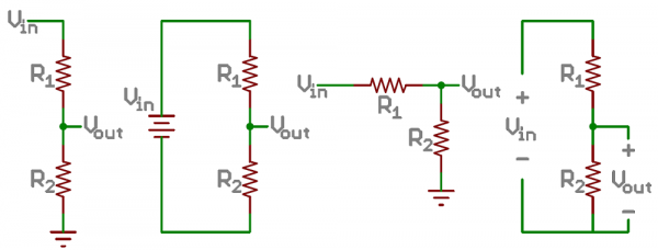
The tricky part was connecting the analog output hygrometer to the analog input of the ESP-12 board. The analog out provides a 0 to 3.3v current (when getting 100 to 0 % moisture respectively). The analog input of the ESP8266 can read between 0 - 1V so we need a voltage divider to get the analog output to give out a current with this range..

Links:
https://learn.sparkfun.com/tutorials/voltage-dividers
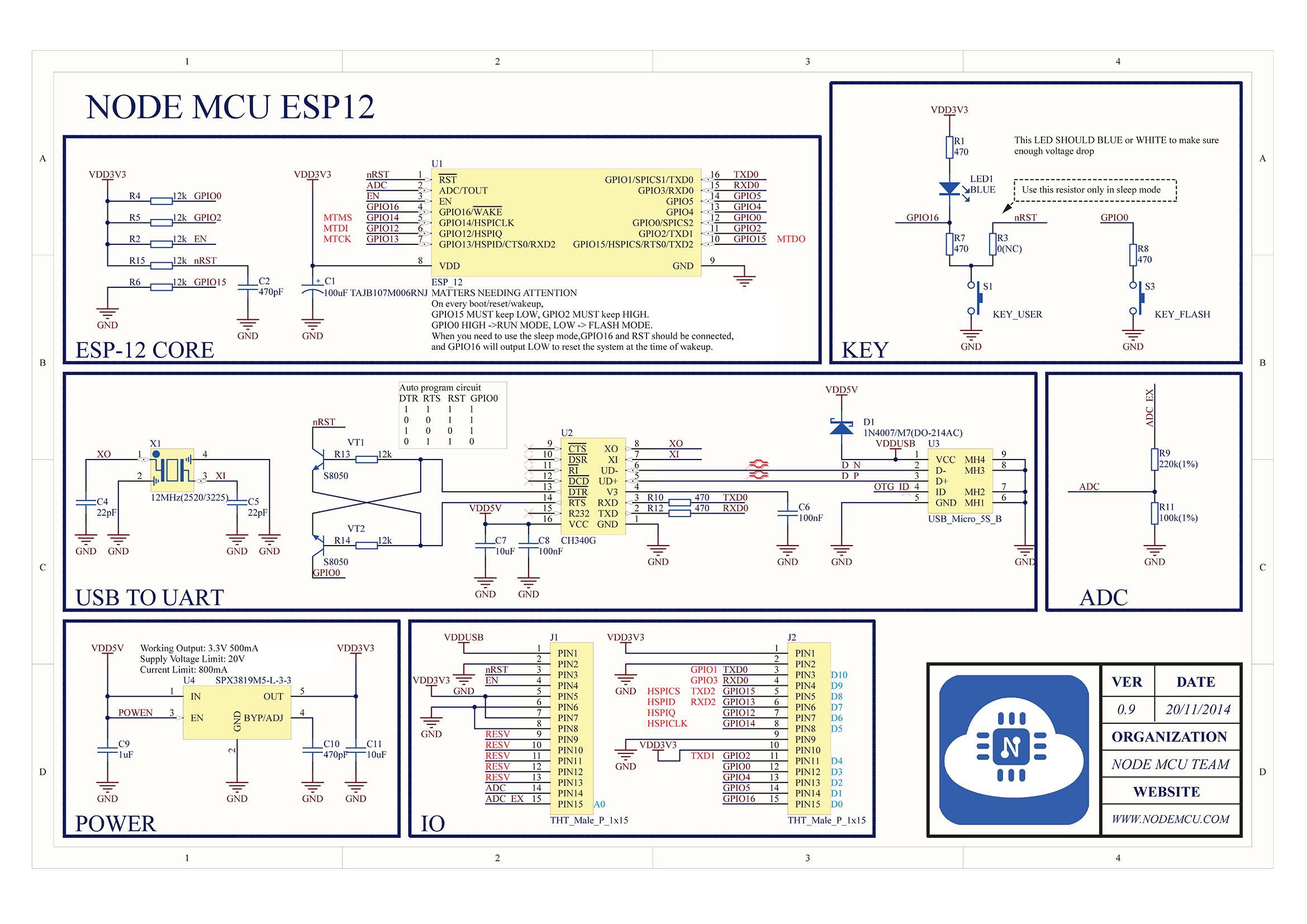
https://raw.githubusercontent.com/nodemcu/nodemcu-devkit/master/Documents/NODEMCU_DEVKIT_SCH.png
https://cdn.sparkfun.com/r/600-600/assets/4/0/3/a/e/511948ffce395f7f47000000.png
No comments:
Post a Comment