The main hub outdoors
Steps:
- Getting 2G/3G connection on start up
- Making the hardware outdoor and weather proof
- Setting up the solar battery infrastructure
Connection to the cloud
We bought a Huawei 303 2G/3G USB stick as we had found it (in many tutorials) to be compatible. We found following this tutorial to be helpful.
Here a quick summary:
- Installed ppp interface:
sudo apt-get install ppp
- Got umtskeeper scripts to maintain connection
- Got sakis3g scripts to build up connection. This tutorial was very helpful.
- Wrote start shell script and added it to /etc/rc.local to connect on start up. Hint: See logfile in /var/log/umtskeeper.log for debugging
#!/bin/sh

/home/pi/umtskeeper/umtskeeper --sakisoperators "USBINTERFACE='0' OTHER='USBMODEM' USBMODEM='12d1:1c05' APN='CUSTOM_APN' CUSTOM_APN='internet' SIM_PIN='XXXX' APN_USER='0' APN_PASS='0'" --sakisswitches "--sudo --console" --devicename 'Huawei' --log --silent --monthstart 8 --nat 'no' --httpserver &>> /home/pi/umtskeeper/error.log &
This is what I appended to the /etc/rc.local file:
#Turn off HDMI to save power
/opt/vc/bin/tvservice -o

#DEBUG USB_MODESWITCH added also an entry to /etc/usb_modeswitch.conf but somehow it doesn't always read the cfg
usb_modeswitch -v 12d1 -p 14fe -M '55534243123456780000000000000011060000000000000000000000000000'

#Sleep before starting gsm
sleep 30

#Starting GSM connectivity
/home/pi/umtskeeper/startGSMConnection

#Sleep before starting ioBroker
sleep 180

#Start iobroker. Removed autostart due to confusion with usb serial and usb 3g stick
/etc/init.d/iobroker.sh start
Preparing for the outdoors
Used an electric drill screwer to drill three holes in to a plastic box and two in to the cover. We will need two sensors (precipitation and partially the BH1750) to be exposed but the rest of the hardware should be encased.
Added the main hub controller (Arduino and sensors) on top of the Pi. and extended cables for BH1750 and precipitation sensor. Also for the INA219. Still waiting for it to arrive.
Both sensors are now exposed and the main hub is ready to go outside.
Main hub power infrastructure
We decided to use a lead gel 8 Ah battery with a 12 V 20 W solar panel and an of the shelf charge regulator. More on why we chose this constellation see our next post.
This might seem a bit to much for a simple gateway application. On the contrary:
- The Raspberry Pi (B) is is consuming about 200 mAh
- The 2G/3G data card is consuming 150 to 180 mAh
- The Wifi card is consuming about 100 to 150 mAh
- We've switched off (actually its in deep sleep) the ESP board on the nanoESP ("AT+GSLP=<time>") to save power
Charge regulator
The charge regulator is a off the shelf product for 12-24V 10 A input. It comes with a power strip with USB output. Unfortunately we could not use the USB port as it provided only 500 mA.
 |
| Comparison: main hub and node charge regulation |
The charge regulator was very easy to set up. All connection are written out on the outlets.
 |
| Charge regulator (very easy to setup) |
 |
| Making it weather proof |
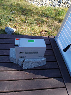
Added wood plates on the grass to elevate all of the components (just in case of heavy rain). I‘ve also put the battery on a piece of concrete.
 |
| Battery on a piece of concrete on wooden plate... |
I covered the battery (temporarily) with a flower pot.
 |
| Solar panel leaning on flowerpot (main hub and charge regulator on the right) |
Voila! Our main hub is now totally independent. To maintain and administrate the main hub I connect to it via its own Wifi access point like the sensor nodes do.
 |
| Everything connected, up and running |


No comments:
Post a Comment