Monday, February 27, 2017

Final report: A quick summary to the project

Final report from the farm:

Our idea:
Building low cost soil moisture sensory system for farmers facing drought with low cost sensors (<$10)  and gateways to easily scale up if necessary. 


Demo from the farm:


An overview of what happened:

  1. Prototyping of the sensor nodes using different types of boards: NanoESP, Arduino Pro Mini, ESP8266: Part #1, #2 and #3 
    Prototype #1

    Prototype #2
  2. We decided to use the ESP8266 (12-F) board and dived deeper into saving power: Part #1 and #2 
  3. Researched solar and battery infrastructures: Part #1 and #2  
  4. Planed and implemented our main hub (Raspberry Pi with Eclipse Mosquitto and ioBroker gateway): Part #1, #2#3 and #4  

  5. The main hub and the nodes are ready to leave the building: Part #1 and #2 


Lessons learned:

  • Building low cost sensory with development boards is easy.
  • Building a reliable solar battery power infrastructure is not. Especially when using deepsleep on ESP8266. Good power regulation to avoid getting stuck in a boot loop is very important.
  • Raspberry Pi (B+) might not be the best choice as a remote (with no power supply) gateway due to its power consumption. However we are not sure that a Raspberry Pi Zero would be able to handle the (current) load. The 2G/3G and Wifi USB stick are also very power thirsty.
  • Power on hygrometers should be turned off when no reading occurs. The sensor end corrode much quicker otherwise. The end of the sensor should be easily replaceable by the farmer. Furthermore, they should be offered in different length as water level might vary with different types of plants.
  • We would have liked to integrate automatic updates of the air (OTA) for our IoT devices firmware to make them more responsive to current and forecasted weather information (i.e. reducing interval of data being sent with bad light intensity to save power).
  • After 4 days of intensive testing our mobile data consumption is at about 12 MB


Final report from the cloud:


Our backend contains 4 components/services, whenever an event from the farm or a command from the cloud is published, it reaches the controller service through an MQTT broker (IBM IoT platform in this case), the controller then process the event by adding the necessary information to the event such as the user and farm information to the event payload then invoke twoOpenWhisk actions. The first action will store the event/command in the historical database (Cassandra) for analytic purposes. The second action is the main action which will determine if a watering command needs to be sent to the farm or not. The watering action uses the active rule of the farm which is a set of conditions (lessThan, greaterThan, Equals, or ignore) for all the data either coming from the farm (sensor events) or the data collected in the cloud (currently weather data) and have a decision whether to water the farm or not. The rule can be created by the farmer using the farmer web application and can activate any rule he wants for his farms.

The other service is the Enricher, this component enriches the farms with more information from third-party services such as the OpenWeather API, this will allow having better watering decision.
The last component is the API, we offer different API endpoints to interact with the system as well as to get analytics and insights such as the last events and commands in a farm.

The following architecture, is an overall overview of our solution:


Farmer demo application :


Controller Service

As soon as the event are emitted, it goes directly using MQTT to IBM IoT platform. Then the controller service receive these events and process them and invoke both the watering and the historian actions in OpenWhisk. Besides that, Any command that generated by the watering action will also be received by the controller and it will invoke the historian action to store this command in the historical database.
 

Enricher Service

This service is the contact point with the third-party services, for now, we are using the OpenWeather API to provide insights over the weather forecasting to support the decision of watering the farms. However in the future, we could enrich the farm data with soil or plant information.
 

API Service

We offer different API endpoints to interact and get analytics and insight information of the different entities in the system. The API is used mainly by the farmer web application that was built using node-red. The API service has the below endpoints:

Devices API

This API endpoint allow different clients to interact with the system by creating, updating, listing and deleting devices as well as retrieving devices by user or farm Ids.

Farms API

Same way to interact with devices, we offer an API to interact with farms by creating, adding and deleting farms as well as retrieving farms by userId.

Rules API

Adding, updating, deleting, listing and retrieving rules by userId are also offered to interact with the rules.

Users API

Above that, we offer also endpoints to interact with the users, adding, updating, listing, deleting and retrieving users by their names.

Historical API

This endpoint allow clients to access our historical database and have analytics and insights information based on the events and commands.


Farmer Web Application

We have built a web application that can be used by the farmer to manage his devices, farms, rules and to see a live feed from the farm sensors. The farmer can create his own custom rules or use some existing rules and activate them for any one of his farms. Once the rule is activated, he will get notifications whenever watering is needed based on his rule. The farmer can also set a non-watering related rules such as to get notification whenever the battery of the sensor nodes are low. Basically the farmer, can create a rule using any of the data that comes from the farm (soil moisture, temperature, light, etc ..) or the data that was collected in the cloud (current weather, forecast weather). The rule is a set of conditions (greaterThan, lessThan, equals, or ignore) for each data. 

Open Technologies Used: 


MQTT: 

We use MQTT as communication medium between the backend components and the fields nodes.

Apache OpenWhisk:

OpenWhisk is an open source serverless cloud platform that execute code and run containers in response to events or direct invocation. We are using OpenWhisk to handle the large number of events in a scalable manner. In our solution, till moment, we have two components hosted on Bluemix OpenWhisk, the watering action and the historical action.

Docker Containers:

Some of the components are deployed as a container, such as cassandra and mongoDB which are deployed on the cloud in containers.

Apache Cassandra: 

Used as a historical database since it is powerful in time series data. We use it to store all events and commands generated by the system.

MongoDB:

MongoDB is our operational database, where we store the entities used and generated in the system, such as the farms and users information.

NodeRED:

We used NodeRED to build the dashboard to allow farmers to interact with the system in a better way.

OpenWeather :

 As we mentioned, we used third-party services to support the decision of watering the farms, OpenWeather is an open source API that provide forecasts over the weather.


Lessons learned  :

1-  Creating a smart service that decides when watering is required based on many different information from sensors in the farm and extra information collected in the cloud, is not an easy task. Currently we are allowing the farmer to decide what rule he wants to create around this data, however in the future, I think we need to use some cognitive services with machine learning capabilities to be able to provide the farmer with some smart rules that he can activate for his farm.
2- Using server-less architecture such as OpenWhisk was a good idea for our use case since we are sending the data from the farm not so frequently (once a day is enough) and this means we execute a watering action only few times which reduce our cost since we don't have to pay for the server runtime all day but only pay for what we execute. Cost is very important factor for our use case.
3- Since our solution is intended to be used by development countries, having internet connection up and running is not always the case. This means we need to provide some kind of edge solution that can work offline until the internet connection is working.

Code of the cloud:

https://github.com/alronz/iotchallenge-backend


Update from Farm-Team: Thinking about power #2: Reading the battery level and our first test results

Conclusion to our prior post: Thinking about power #1

Sensor node prototype #2


For our nodes we have decided to use:

  • Led-Acid battery for our main hub 
    • Overcharge tolerance 
    • Low self discharge 
    • Low maintenance 
    • Low price 
  • Li-Ion/NiCd battery for our sensor nodes 
    • Li-Ion due to the availability of cheap charge regulators (i.g. TP4056 <$1) 
    • Fast charge capabilities 
    • High number of (life) cycles 
    • Low price 

Useful links:

  • Very handy comparison of batteries: link
  • Very handy comparison of Li-Ion and NiMh batteries: link
  • Battery charging in relation to temperature: link


Battery charging:
We won't go into to much detail here. We recommend initially using a charge balancer to avoid damaging the battery. Furthermore, overcharging the battery or to quickly discharging battery may be dangerous (fire hazard). 


Choosing the right solar panel depends on the battery type and its charging advisory ("C"). 

We found these tutorials to be helpful: 1, 2 and 3.

Battery level (SOC):


After we researched how to measure battery load (level) we have realised that there is no real easy way to do this but to calculate and estimate a value.

Possible ways to do that:

  • From the voltage (in combination with the temperature) we can find out when the battery is full or is about to be empty. We need the temperature for this as it affects the battery efficiency and its output voltage
  • Or better: We can measure the current and find out how much is being consumed and estimate from the time the battery was full (voltage) the remaining battery life
  • Our main hub also measures light intensity so (as an example) on a cloudy day with battery level we can predict a power shortage and recommend to the user to manually recharge


Charge time in relation to temperature for NiCd

For the main hub we decided to measure current and voltage to determine the SOC. For the sensor nodes we will use the voltage and calculate and predict shortages using the light intensity measurements.
We found this and this tutorial to be very helpful.


    Shopping:

  • 16 channel analog digital Multiplexer Modul CD74HC4067
  • INA219 I2C Bi-directional DC Current Power Supply Sensor 


Sensor nodes

We got the analog multiplexer as the ESP8266 board supplies only one ADC input. We don't need 16 channels however we were not able to find a smaller module with the submission deadline of the challenge advancing. On the other hand, we could add another 14 hygrometer (moisture sensors) to get more readings like for a smaller area with smaller plants.

So set up the analog multiplexer we found this tutorial to be very helpful.
Sensor node final with voltage meter

Now that the multiplexer divides the 3.3 V to 1 V we had no need for the voltage divider we had set up before. How ever the battery voltage at full charge is 4.2 V and we have to get that down to 3.3 V. We used a 1,3 and 5 kOhm respectively. So we get about 1 V  reading on a fully charged battery and about 700mV on a half to almost empty battery level. We will be sending this value to the main hub.


Here is our final code for our sensor node:

 /*  
  *   
  * Smartwatering: Eclipse IoT Challenge  
  * Sensor node  
  *   
  */  
 #include <ESP8266WiFi.h>  
 #include <PubSubClient.h>  
 //Digital pins for Analog multiplexer  
 #define AMUXSEL0 14   // AMUX Selector 0  
 #define AMUXSEL1 12   // AMUX Selector 1  
 #define AMUXSEL2 13   // AMUX Selector 2  
 WiFiClient espClient;  
 PubSubClient client(espClient);  
 long lastMsg = 0;  
 char msg[50];  
 int moisture, battery;  
 int sensorValue = 0;  
 int sensorPin = A0; //ADC pin  
 boolean testmode = true;   
 // Update these with values suitable for your network.  
 const char* ssid = "FarmHub";  
 const char* password = "xxxxxxxxxxxxx";  
 const char* mqtt_server = "192.168.1.1";  
 void setup() {  
  pinMode(AMUXSEL0 , OUTPUT); //Pin 14 for Channel 0 and 1 of the Analog multiplexer  
  Serial.begin(9600);  
  setup_wifi();  
  client.setServer(mqtt_server, 1883);  
  client.setCallback(callback);  
  if (!client.connected()) {  
   reconnect();  
   while (!client.connected()) {  
      Serial.print(".");  
      delay(500);  
    }  
   }  
  client.publish("channel21", "Node connected");  
  sensorValue = analogRead(sensorPin);  
  Serial.println("Moisture voltage: " + String(sensorValue));  
  sensorValue = constrain (sensorValue, 240, 1024);  
  moisture = map (sensorValue, 240, 1024, 100, 0);  
  snprintf (msg, 75, "%ld", moisture);  
  Serial.print("Publish message: ");  
  Serial.println(msg);  
  client.publish("moisture", msg);  
  //Setting pin 14 on high to switch from channel 0 to 1  
  digitalWrite(AMUXSEL0, HIGH);  
  delay(500);  
  sensorValue = analogRead(sensorPin);  
  Serial.println("Battery voltage: " + String(sensorValue));  
  battery = map (sensorValue, 0, 1024, 100, 0);  
  snprintf (msg, 75, "%ld", battery);  
  Serial.print("Publish battery message: ");  
  Serial.println(msg);  
  client.publish("battery", msg);  
  delay(500);  
  //Setting pin 14 on low to switch from channel 1 to 0  
  digitalWrite(AMUXSEL0, LOW);  
  delay(500);  
  client.publish("channel21", "Node disconnected");  
  client.disconnect();     
  WiFi.disconnect();  
  //Go to sleep for about 30 minutes  
  ESP.deepSleep(2000 * 1000000);  
  delay(100);  
 }  
 void setup_wifi() {  
  delay(10);  
  // We start by connecting to a WiFi network  
  Serial.println();  
  Serial.print("Connecting to ");  
  Serial.println(ssid);  
  WiFi.begin(ssid, password);  
  while (WiFi.status() != WL_CONNECTED) {  
   delay(500);  
   Serial.print(".");  
  }  
  Serial.println("");  
  Serial.println("WiFi connected");  
  Serial.println("IP address: ");  
  Serial.println(WiFi.localIP());  
 }  
 void callback(char* topic, byte* payload, unsigned int length) {  
  Serial.print("Message arrived [");  
  Serial.print(topic);  
  Serial.print("] ");  
  for (int i = 0; i < length; i++) {  
   Serial.print((char)payload[i]);  
  }  
  Serial.println();  
  // Switch on the LED if an 1 was received as first character  
  if ((char)payload[0] == '1') {  
   // digitalWrite(BUILTIN_LED, LOW);  // Turn the LED on (Note that LOW is the voltage level  
   // but actually the LED is on; this is because  
   // it is acive low on the ESP-01)  
  } else {  
   //digitalWrite(BUILTIN_LED, HIGH); // Turn the LED off by making the voltage HIGH  
  }  
 }  
 void reconnect() {  
  // Loop until we're reconnected  
  while (!client.connected()) {  
   Serial.print("Attempting MQTT connection...");  
   // Attempt to connect  
   if (client.connect("ESP8266Client")) {  
    Serial.println("connected");  
    // Once connected, publish an announcement...  
    client.publish("channel21", "Node connected");  
    // ... and resubscribe  
    client.subscribe("channel21");  
   } else {  
    Serial.print("failed, rc=");  
    Serial.print(client.state());  
    Serial.println(" try again in 5 seconds");  
    // Wait 5 seconds before retrying  
    delay(5000);  
   }  
  }  
 }  
 void loop() {  
 }  


Main hub

Connecting the INA219 was easy as it has an I2C interface and we already had a I2C multiplexer with two sensors connected to it. Now we are getting the following additional measurements:
  •   shunt voltage
  •   bus voltage
  •   current
And we can calculate the  load voltage = bus voltage + (shunt voltage / 1000)

Here is our final code:

 /*  
  *   
  * Smartwatering: Eclipse IoT Challenge  
  * Main hub  
  *   
  */  
 //Libraries  
 #include <DHT.h>  
 #include <BH1750.h>  
 #include <Adafruit_BMP085.h>  
 #include <NanoESP.h>  
 #include <SoftwareSerial.h>  
 #include <Adafruit_INA219.h>  
 #include <Wire.h>  
 //I2C Mux Addr  
 #define TCAADDR 0x70  
 //nanoespdebug  
 #define DEBUG false  
 //Constants  
 #define DHTPIN 2   // what pin we're connected to  
 #define DHTTYPE DHT22  // DHT 22 (AM2302)  
 DHT dht(DHTPIN, DHTTYPE); //// Initialize DHT sensor for normal 16mhz Arduino  
 BH1750 lightMeter;  
 Adafruit_BMP085 bmp;  
 Adafruit_INA219 ina219;  
 NanoESP nanoesp = NanoESP();  
 int sensorValue = 0;  
 int rain = 0;  
 int sensorPin = A0;  
 //int voltage, current;  
 void tcaselect(uint8_t i) {  
  if (i > 7) return;  
  Wire.beginTransmission(TCAADDR);  
  Wire.write(1 << i);  
  Wire.endTransmission();   
 }  
 void setup()   
 {  
  Serial.begin(19200);  
  nanoesp.init(DEBUG);  
  /* Initialise the 1st sensor */  
  tcaselect(2);  
  lightMeter.begin();  
  delay(500);  
  /* Initialise the 2nd sensor */  
  tcaselect(4);  
  ina219.begin();  
  delay(500);  
  /* Initialise the 3rd sensor etc*/  
  tcaselect(6);  
  if(!bmp.begin())  
  {  
   /* There was a problem detecting the BMP ... check your connections */  
   Serial.println("Ooops, no BMP detected ... Check your wiring!");  
   while(1);  
  }  
  /* Dht22 init */  
   dht.begin();  
 }  
 void loop()   
 {  
  //Sending esp board to deep sleep to save power  
  nanoesp.sendCom("AT+GSLP=1000000");  
  //Going through sensors to get values, tca select is used to multiplex i2c  
  tcaselect(2);  
  displaySensorDetailsBH();  
  delay(500);  
  tcaselect(6);  
  displaySensorDetailsBMP();  
  delay(500);  
  displaySensorDetailsDHT();  
  delay(500);  
  displaySensorDetailsRain();  
  delay(500);  
  tcaselect(4);  
  displaySensorDetailsPower();  
  delay(1000000);  
 }  
 void displaySensorDetailsBH() {  
  uint16_t lux = lightMeter.readLightLevel();  
  Serial.print("{\"d\":{");  
  Serial.print("\"");  
  Serial.print("light");  
  Serial.print("\" : ");  
  Serial.print(lux);  
  Serial.print(",");  
 }  
 void displaySensorDetailsBMP() {  
  Serial.print("\"");  
  Serial.print("temperature1");  
  Serial.print("\" : ");  
  Serial.print(bmp.readTemperature());  
  Serial.print(", \"");  
  Serial.print("pressure");  
  Serial.print("\" : ");  
  Serial.print(bmp.readPressure());  
  Serial.print(", \"");  
  // Calculate altitude assuming 'standard' barometric  
  // pressure of 1013.25 millibar = 101325 Pascal  
  Serial.print("altitude");  
  Serial.print("\" : ");  
  Serial.print(bmp.readAltitude());  
  Serial.print(", \"");  
  Serial.print("calculatedpressureatsealevel");  
  Serial.print("\" : ");  
  Serial.print(bmp.readSealevelPressure());  
  // you can get a more precise measurement of altitude  
  // if you know the current sea level pressure which will  
  // vary with weather and such. If it is 1015 millibars  
  // that is equal to 101500 Pascals.  
  Serial.print(", \"");  
  Serial.print("realaltitude");  
  Serial.print("\" : ");  
  Serial.print(bmp.readAltitude(101500));  
  Serial.print(",");  
 }  
 void displaySensorDetailsDHT() {  
   float h = dht.readHumidity(); //Luftfeuchte auslesen  
   float t = dht.readTemperature(); //Temperatur auslesen  
   // Prüfen ob eine gültige Zahl zurückgegeben wird. Wenn NaN (not a number) zurückgegeben wird, dann Fehler ausgeben.  
   if (isnan(t) || isnan(h))   
   {  
   Serial.println("DHT22 konnte nicht ausgelesen werden");  
   }   
   else  
   {  
   Serial.print("\"");  
   Serial.print("humidity");  
   Serial.print("\" : ");  
   Serial.print(h);  
   Serial.print(", ");  
   Serial.print("\"");  
   Serial.print("temperature2");  
   Serial.print("\" : ");  
   Serial.print(t);  
   Serial.print(",");  
  }  
 }  
 void displaySensorDetailsRain() {  
  sensorValue = analogRead(sensorPin);  
  rain = map (sensorValue, 250, 1024, 100, 0);  
  Serial.print("\"");  
  Serial.print("rain");  
  Serial.print("\" : ");  
  Serial.print(rain);  
 }  
  void displaySensorDetailsPower() {  
  float shuntvoltage = 0;  
  float busvoltage = 0;  
  float current_mA = 0;  
  float loadvoltage = 0;  
  shuntvoltage = ina219.getShuntVoltage_mV();  
  busvoltage = ina219.getBusVoltage_V();  
  current_mA = ina219.getCurrent_mA();  
  loadvoltage = busvoltage + (shuntvoltage / 1000);  
  Serial.print(",\"busVoltage \": "); Serial.print(busvoltage);   
  Serial.print(",\"shuntVoltage \": "); Serial.print(shuntvoltage);   
  Serial.print(",\"loadVoltage\" : "); Serial.print(loadvoltage);   
  Serial.print(",\"current\" : "); Serial.print(current_mA);   
  Serial.print("}}");  
  Serial.println();  
 }  


Saturday, February 25, 2017

Update from Farm-Team: The main hub outdoors


The main hub outdoors


Steps:

  • Getting 2G/3G connection on start up
  • Making the hardware outdoor and weather proof
  • Setting up the solar battery infrastructure

Connection to the cloud

We bought a Huawei 303 2G/3G USB stick as we had found it (in many tutorials) to be compatible. We found following this tutorial to be helpful. 

Here a quick summary:
  1. Installed ppp interface:  
    sudo apt-get install ppp
  2. Got umtskeeper scripts to maintain connection
  3. Got sakis3g scripts to build up connection. This tutorial was very helpful.
  4. Wrote start shell script and added it to /etc/rc.local to connect on start up. Hint: See logfile in /var/log/umtskeeper.log for debugging
    #!/bin/sh
    
    /home/pi/umtskeeper/umtskeeper --sakisoperators "USBINTERFACE='0' OTHER='USBMODEM' USBMODEM='12d1:1c05' APN='CUSTOM_APN' CUSTOM_APN='internet' SIM_PIN='XXXX' APN_USER='0' APN_PASS='0'" --sakisswitches "--sudo --console" --devicename 'Huawei' --log --silent --monthstart 8 --nat 'no' --httpserver &>> /home/pi/umtskeeper/error.log &

This is what I appended to the /etc/rc.local file:

#Turn off HDMI to save power
/opt/vc/bin/tvservice -o

#DEBUG USB_MODESWITCH added also an entry to /etc/usb_modeswitch.conf but somehow it doesn't always read the cfg 
usb_modeswitch -v 12d1 -p 14fe -M '55534243123456780000000000000011060000000000000000000000000000'

#Sleep before starting gsm
sleep 30

#Starting GSM connectivity
/home/pi/umtskeeper/startGSMConnection

#Sleep before starting ioBroker
sleep 180

#Start iobroker. Removed autostart due to confusion with usb serial and usb 3g stick 
/etc/init.d/iobroker.sh start

Preparing for the outdoors

Used an electric drill screwer to drill three holes in to a plastic box and two in to the cover. We will need two sensors (precipitation and partially the BH1750) to be exposed but the rest of the hardware should be encased. 


Added the main hub controller (Arduino and sensors) on top of the Pi. and extended cables for BH1750 and precipitation sensor. Also for the INA219. Still waiting for it to arrive.


Both sensors are now exposed and the main hub is ready to go outside. 


Main hub power infrastructure

We decided to use a lead gel 8 Ah battery with a 12 V 20 W solar panel and an of the shelf charge regulator. More on why we chose this constellation see our next post.

This might seem a bit to much for a simple gateway application. On the contrary:
  • The Raspberry Pi (B) is is consuming about 200 mAh
  • The 2G/3G data card is consuming 150 to 180 mAh
  • The Wifi card is consuming about 100 to 150 mAh
  • We've switched off (actually its in deep sleep) the ESP board on the nanoESP ("AT+GSLP=<time>") to save power

Charge regulator

The charge regulator is a off the shelf product for 12-24V 10 A input. It comes with a power strip with USB output. Unfortunately we could not use the USB port as it provided only 500 mA.
Comparison: main hub and node charge regulation 


The charge regulator was very easy to set up. All connection are written out on the outlets.
Charge regulator (very easy to setup)
I've used a second plastic box to encase it.
Making it weather proof

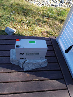
Added wood plates on the grass to elevate all of the components (just in case of heavy rain). I‘ve also put the battery on a piece of concrete.  
Battery on a piece of concrete on wooden plate... 

I covered the battery (temporarily) with a flower pot.
Solar panel leaning on flowerpot (main hub and charge regulator on the right)


Voila! Our main hub is now totally independent. To maintain and administrate the main hub I connect to it via its own Wifi access point like the sensor nodes do.
Everything connected, up and running


Wednesday, February 22, 2017

Update from Farm-Team: Information flow on the ioBroker

Main hub IO

We have our wireless sensor nodes sending in information over MQTT to the Eclipse Mosquitto broker (localhost) and we have the main hub controller sending data over serial.

We are using Node-RED flows for the receiving and sending end.

Input

Main hub sensor

Our Node-RED flow is very simple as you will see on the screenshot below. We already mentioned in an earlier blog that we send the data in form of JSON over serial from the nanoESP.


Flow:

Data coming over serial port (node-red-node-serialport) => JSON conversion to object => next is a simple JavaScript function that breaks down the object (see code on the right) => and writes the values to ioBroker objects

This is how the ioBroker retains the data:

We added the history node (adapter), which is a multifunctional (in memory and on disk) database. The objects can be setup to be stored in the database.


Enabling the data retention

Table with historical values

Sensor nodes

Our sensor nodes are sending data to our Eclipse Mosquitto broker in the main hub.

Flow:

MQTT listener (mqtt) listening to topic moisture (as an example as we have more than one) => and writes the values to ioBroker objects. The data is retained like we showed before.


Output

Due to us sending data over GSM/Edge we will stich the main hub and sensor data together to avoid sending to many packages as the number of sensor nodes are not limited (and we can monitor a defined message standard better). We have written a script that does just that (stitching) using the Javascript node (adapter). This is basically a JavaScript IDE for the ioBroker.

This code runs every ten seconds and reads all the measurement objects in the database and writes it all to a JSON array in an ioBroker object.


Script:

 schedule("*/10 * * * * *", function () {  
   var altitude = getState('node-red.0.smartwatering.mainhub.altitude');  
   var calcpressuresealevel = getState('node-red.0.smartwatering.mainhub.calcpressuresealevel');  
   var humidity = getState('node-red.0.smartwatering.mainhub.humidity');  
   var light = getState('node-red.0.smartwatering.mainhub.light');  
   var pressure = getState('node-red.0.smartwatering.mainhub.pressure');  
   var rain = getState('node-red.0.smartwatering.mainhub.rain');  
   var realaltitude = getState('node-red.0.smartwatering.mainhub.realaltitude');  
   var temperature1 = getState('node-red.0.smartwatering.mainhub.temperature1');  
   var temperature2 = getState('node-red.0.smartwatering.mainhub.temperature2');  
   var soilmoisture1 = getState('node-red.0.smartwatering.sensornodes.soilmoisture1');  
   var soilmoisture2 = getState('node-red.0.smartwatering.sensornodes.soilmoisture2');  
   var soilmoisture3 = getState('node-red.0.smartwatering.sensornodes.soilmoisture3');  
   var soilmoisture4 = getState('node-red.0.smartwatering.sensornodes.soilmoisture4');  
   var sensordataobj = '{\"d\" : { \"altitude\" : ' + JSON.stringify(altitude)   
   + ', \"calcpressuresealevel\" : ' + JSON.stringify(calcpressuresealevel)  
   + ', \"humidity\" : ' + JSON.stringify(humidity)  
   + ', \"light\" : ' + JSON.stringify(light)   
   + ', \"pressure\" : ' + JSON.stringify(pressure)   
   + ', \"rain\" : ' + JSON.stringify(rain)   
   + ', \"realaltitude\" : ' + JSON.stringify(realaltitude)   
   + ', \"temperature1\" : ' + JSON.stringify(temperature1)   
   + ', \"temperature2\" : ' + JSON.stringify(temperature2)   
   + ', \"soilmoisture1\" : ' + JSON.stringify(soilmoisture1)  
   + ', \"soilmoisture2\" : ' + JSON.stringify(soilmoisture2)  
   + ', \"soilmoisture3\" : ' + JSON.stringify(soilmoisture3)   
   + ', \"soilmoisture4\" : ' + JSON.stringify(soilmoisture4)  
   +'}}';  
   createState('sensordataobj');  
   setState('sensordataobj', sensordataobj);  
   console.log(sensordataobj);  
 });  


So now that we have all of our data in an object (called "sensordataobj) we send it all to our cloud using Node-RED:


Flow:

At an interval of 3 minutes (testing) => we send the object sensordataobj as an array => to the cloud using the IBMIoT node (node-red-contrib-scx-ibmiotapp and node-red-contrib-iotclouddev

The quick start mode allows us to see the result (without any registration to the platform) using the MAC address of our main hub as device id:


The data we are sending to the cloud looks like this:
  {“d” : { "altitude" : {"val":421.48,"ack":true,"ts":1486933460625,"q":0,"from":"system.adapter.node-red.0","lc":1486933460625}, "calcpressuresealevel" : {"val":96365,"ack":true,"ts":1486933460634,"q":0,"from":"system.adapter.node-red.0","lc":1486933460634}, "humidity" : {"val":54,"ack":true,"ts":1486933460647,"q":0,"from":"system.adapter.node-red.0","lc":1486933419447}, "light" : {"val":63,"ack":true,"ts":1486933460409,"q":0,"from":"system.adapter.node-red.0","lc":1486932505750}, "pressure" : {"val":96365,"ack":true,"ts":1486933460576,"q":0,"from":"system.adapter.node-red.0","lc":1486933460576}, "rain" : {"val":106,"ack":true,"ts":1486933460660,"q":0,"from":"system.adapter.node-red.0","lc":1486933460660}, "realaltitude" : {"val":435.81,"ack":true,"ts":1486933460641,"q":0,"from":"system.adapter.node-red.0","lc":1486933460641}, "temperature1" : {"val":22.5,"ack":true,"ts":1486933460467,"q":0,"from":"system.adapter.node-red.0","lc":1486933460467}, "temperature2" : {"val":21.9,"ack":true,"ts":1486933460654,"q":0,"from":"system.adapter.node-red.0","lc":1486931918181}, "soilmoisture1" : {"val":"91","ack":true,"ts":1486933451665,"q":0,"from":"system.adapter.node-red.0","lc":1486923522504}, "soilmoisture2" : {"val":"91","ack":true,"ts":1486933451665,"q":0,"from":"system.adapter.node-red.0","lc":1486923522504}, "soilmoisture3" : {"val":"91","ack":true,"ts":1486933451665,"q":0,"from":"system.adapter.node-red.0","lc":1486923522504}, "soilmoisture4" : {"val":"91","ack":true,"ts":1486933451665,"q":0,"from":"system.adapter.node-red.0","lc":1486923522504}}}  

See link for description of meta data.

Monday, February 20, 2017

Update from Farm-Team: Main hub server part 2 (introducing the ioBroker)

In our proposal we had planned to use Eclipse Kura project as our main gateway platform. Due to a change in our team structure we (the farm team) were short of a second developer.

At the beginning, and during the first tests we were using an open source message broker called the ioBroker as our main gateway platform. With the submission deadline advancing we decided to stick to the ioBroker as we had prior experience with it and already had configured the server which gave us all the features we needed.

The ioBroker is a Node.js based open source platform which is ARM and x86/x64 compatible. It integrates a lot of other open source nodes (adapters) and provides us with the following features:

  • Object and state management: Data retention and management
  • Node-RED: Quick prototyping and an easy way to wire up all of the devices, listener, APIs, etc). 
  • Easy remote system administration with a web application
  • User management, multiple UI possibilities and much more... (see our next blog posts)


The Github page states the following:
"ioBroker is an integration platform for the Internet of Things, focused on Building Automation, Smart Metering, Ambient Assisted Living, Process Automation, Visualization and Data Logging. It like a software f.e. fhem, OpenHABor the thing system."

See Github link below

Installing the ioBroker on the Raspberry Pi

A detailed set of instructions can be found here. Please note that the Raspberry Pi (1) needs a different version of Node.js than the one provided in the Raspbian repositories. 

After installing the ioBroker you should be able to start it by call the iobroker script in your ioBroker root directory. This script basicall calls the iobroker.js-controller (controller.js) script with Node.js. Make sure that you have a symbolic link from "node" to "nodejs". You can check this by typing:

node -v 

on your command line.

Otherwise add the symbolic link with:

sudo ln -s /usr/local/bin/nodejs /usr/bin/node

If everything is good you can start the iobroker with

iobroker start

Go to http://<youripadress>:8081/

You should see the iobroker.admin web application.


Installing Node-RED:


One can easily install Node-RED from the admin web app:


or in the command line (iobroker root directory):

iobroker install <adapter> (in this case the adapter is called iobroker.node-red)

or you can directly install it by using npm:

npm install iobroker.node-red

Other adapters (nodes) can be installed in the same way.

Administrating your adapters (nodes aka instances)

This can be done from the instances tab in the admin web interface:

Or from the command line interface:


Links:
https://github.com/iobroker/iobroker
https://www.npmjs.com/package/iobroker.node-red
https://nodered.org/
http://www.iobroker.net/?page_id=5106&lang=de

Wednesday, February 15, 2017

Update from the Farm-Team: Main hub server part one with the Eclipse Mosquitto MQTT broker

In this post we will be talking about setting up our Main hub (Raspberry Pi) with Eclipse Mosquitto and Paho for MQTT and communicating with our main hub controller (nanoESP).

We are using a Raspberry Pi Model B+ with the current Raspbian (Jessie) and a 32 GB SD card. As we are still waiting to receive our GSM/UMTS interface we are using the eth0 interface instead for the communication towards the cloud.


For the communication between Arduino and the Raspberry Pi we don't have to really dive in to that. As we are printing the data on serial (see prior blog post) we will briefly mention our setup and dive more in to local data aggregation, retention and other details details.

Setting up Eclipse Mosquitto

Setting up Eclipse Mosquitto on Raspbian was really easy as its available in the Raspbian main repository. On the command line:

sudo apt-get install mosquitto

Check if the service is running by using:

sudo service mosquitto status

We found this tutorial and discovered FHEM on the way. FHEM is an interesting Perl based open source platform which acts a message broker and visualisation aid. However we decided to go with another platform. More about that in our next post. 

You can test if your MQTT broker ist getting anything by executing (on CLI):

mosquitto_sub -t TopicName


Connecting Raspberry Pi to Arduino

At first we found this tutorial to be very helpful. We did this connection both over the Raspberry Pi GPIO and later on over USB (see prior blog post).  Creating the following Python script to write the values to a file:

 from __future__ import print_function   
 import serial  
 import time  
 s = serial.Serial('/dev/ttyUSB0', 19200) # Namen ggf. anpassen  
 s.isOpen()  
 time.sleep(5) # der Arduino resettet nach einer Seriellen Verbindung, daher muss kurz gewartet werden  
 #s.write("test")  
 try:  
   while True:  
     response = s.readline()  
     print(response)  
     f = open('workfile', 'a')  
     line = response + '\n'   
     f.write(line) # python will convert \n to os.linesep  
     f.close() # you can omit in most cases as the destructor will call it  
 except KeyboardInterrupt:  
   s.close()  

The "workfile" contains following entries:


So now that we are getting the values from our Raspberry Pi, we also used Paho (with this tutorial) to directly publish the values received over serial:

 #!/usr/bin/env python  
 import serial  
 import time  
 import paho.mqtt.client as mqtt  
 def on_connect(client, userdata, flags, rc):  
   print("Connected with result code " + str(rc))  
 client = mqtt.Client()  
 client.on_connect = on_connect  
 client.connect("iot.eclipse.org", 1883, 60)  
 client.loop_start()  
 s = serial.Serial('/dev/ttyUSB0', 19200) # Namen ggf. anpassen  
 s.isOpen()  
 time.sleep(5) # der Arduino resettet nach einer Seriellen Verbindung, daher muss kurz gewartet werden  
 s.write("test")  
 try:  
   while True:  
     response = s.readline()  
     print(response)  
     time.sleep(2)  
     client.publish("moisture", response)  
 except KeyboardInterrupt:  
   s.close()  

Setting up a wifi access point

We bought a wifi USB stick for about 4 €. The stick is compatible to Linux and works right out of the box and can be in AP mode. The wireless access point is used by the sensor nodes. They wake up once every hour and connect to it. We used the following tutorial to install hostapd and dnsmasq on the Raspberry Pi and set the needed configuration.

Links:
https://tutorials-raspberrypi.de/arduino-raspberry-pi-miteinander-kommunizieren-lassen/
https://www.elektronik-kompendium.de/sites/raspberry-pi/2002171.htm
https://pypi.python.org/pypi/paho-mqtt/1.1

Wednesday, February 8, 2017

Update from Farm-Team: Ideas for the main hub our gateway to the cloud

For our main hub we early on defined the following requirements/specifications:

The main hub operates as:
  • Central sensors (temperature, humidity, light intensity, pressure etc.). Sensors:
    • DHT22
    • BH1750
    • BMP180
    • Analog precipitation sensor
  • Wifi access point for the sensor nodes
  • MQTT broker also for the sensor nodes
  • MQTT/IBMIoT client to the cloud
  • Database/dataspool for measurement values
  • Remote administration console
Lets us first start with the main hub controller:
The general idea is connection the controller directly to the Raspberry Pi (Model B+)  via UART (serial).

We will be using the nanoESP board we used before. Again, this only a dev board built on the basis of a Arduino Nano board plus an ESP8266 board, which is sold by Conrad Electronics, an electronics retailer in Germany. On our board drawings and schematics you will see a Arduino Nano board connected to an ESP8266 board. Also instead of a analog precipitation sensor we are using a soil moisture sensor and the light intensity sensor on the drawing is not the identical one we are using.
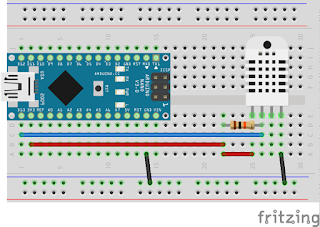
Connecting BH1750 and BMP180 to the board: As we will be using two sensors that require I2C communication via the A4 and A5 pins on the Arduino we will be using a I2C multiplexer from Ardafruit (SCL/SDA). I found this tutorial to be very helpful. 
Example from tutorial (with two identical sensors)


Connecting the DHT22 sensor: This can be directly connected to a digital GPIO on the Arduino. Pretty straight forward: A lot of tutorials on the web for this step:

Example from tutorial (Arduino Nano & DHT22 sensor)

After connecting the precipitation sensor to A0 (see next illustration), we can now focus on connecting nanoESP board to our Raspberry Pi. For this step I recommend a look at this tutorial.
The tutorial explains how to connect via level shift converter or a voltage divider as the Raspberry Pi GPIO operate at a lower voltage. The easiest way though is to connect the Raspberry Pi to the Arduino Nano via USB cable as this saves you from needing further current regulation but also supplies the board with a regulated power source.

After the final step:

Final setup

Main hub controller schematics


The code

The code loops through all sensors and builds a json-String. This is the printed to serial.

 #include <Wire.h>  
 //Libraries  
 #include <DHT.h>  
 #include <BH1750.h>  
 #include <Adafruit_BMP085.h>  
 #define TCAADDR 0x70  
 //Constants  
 #define DHTPIN 2   // what pin we're connected to  
 #define DHTTYPE DHT22  // DHT 22 (AM2302)  
 DHT dht(DHTPIN, DHTTYPE); //// Initialize DHT sensor for normal 16mhz Arduino  
 int sensorValue = 0;  
 int humidity;  
 int sensorPin = A0;  
 BH1750 lightMeter;  
 Adafruit_BMP085 bmp;  
 void tcaselect(uint8_t i) {  //function to switch I2C multiplexer
  if (i > 7) return;  
  Wire.beginTransmission(TCAADDR);  
  Wire.write(1 << i);  
  Wire.endTransmission();   
 }  
 void setup(void)   
 {  
  Serial.begin(19200);  
  //Serial.println("Sensor Test"); Serial.println("");  
  /* Initialise the 1st sensor */  
  tcaselect(2);  //switch to and start BH1750
  lightMeter.begin();  
 // if(!lightMeter.begin())  
 // {  
   /* There was a problem detecting the HMC5883 ... check your connections */  
 //  Serial.println("Ooops, no Lightmeter detected ... Check your wiring!");  
  //  while(1);  
 // }  
  delay(500);  
  /* Initialise the 2nd sensor */  
  tcaselect(6);  //switch to and start BMP180
  if(!bmp.begin())  
  {  
   /* There was a problem detecting the HMC5883 ... check your connections */  
   Serial.println("Ooops, no BMP detected ... Check your wiring!");  
   while(1);  
   dht.begin();  
  }  
 }  
 void loop(void)   
 {  
  tcaselect(2);  
  displaySensorDetails();  
  delay(500);  
  tcaselect(6);  
  displaySensorDetailsBMP();  
  delay(500);  
  displaySensorDetailsDHT();  
  delay(500);  
  displaySensorDetailsRain();  
  delay(1000);  
 }  
 void displaySensorDetails() {  
  uint16_t lux = lightMeter.readLightLevel();  
  Serial.print("{\"d\":{");  
  Serial.print("\"");  
  Serial.print("light");  
  Serial.print("\" : ");  
  Serial.print(lux);  
  Serial.print("}}");  
  Serial.println();  
  delay(1000);  
  }  
 void displaySensorDetailsBMP() {  
  Serial.print("{\"d\":{");  
  Serial.print("\"");  
  Serial.print("temperature1");  
  Serial.print("\" : ");  
  Serial.print(bmp.readTemperature());  
  Serial.print(", \"");  
  Serial.print("pressure");  
  Serial.print("\" : ");  
  Serial.print(bmp.readPressure());  
  Serial.print(", \"");  
  // Calculate altitude assuming 'standard' barometric  
  // pressure of 1013.25 millibar = 101325 Pascal  
  Serial.print("altitude");  
  Serial.print("\" : ");  
  Serial.print(bmp.readAltitude());  
  Serial.print(", \"");  
  Serial.print("calculatedpressureatsealevel");  
  Serial.print("\" : ");  
  Serial.print(bmp.readSealevelPressure());  
 // you can get a more precise measurement of altitude  
 // if you know the current sea level pressure which will  
 // vary with weather and such. If it is 1015 millibars  
 // that is equal to 101500 Pascals.  
  Serial.print(", \"");  
  Serial.print("realaltitude");  
  Serial.print("\" : ");  
  Serial.print(bmp.readAltitude(101500));  
  Serial.print("}}");  
  Serial.println();  
  //Serial.println();  
  delay(1000);  
 }  
 void displaySensorDetailsDHT() {  
   float h = dht.readHumidity(); //Luftfeuchte auslesen  
   float t = dht.readTemperature(); //Temperatur auslesen  
   // Prüfen ob eine gültige Zahl zurückgegeben wird. Wenn NaN (not a number) zurückgegeben wird, dann Fehler ausgeben.  
   if (isnan(t) || isnan(h))   
   {  
   Serial.println("DHT22 konnte nicht ausgelesen werden");  
   }   
   else  
   {  
   Serial.print("{\"d\":{");  
   Serial.print("\"");  
   Serial.print("humidity");  
   Serial.print("\" : ");  
   Serial.print(h);  
   Serial.print(", ");  
   Serial.print("\"");  
   Serial.print("temperature2");  
   Serial.print("\" : ");  
   Serial.print(t);  
   Serial.print("}}");  
   Serial.println();  
  }  
  }  
 void displaySensorDetailsRain() {  
  sensorValue = analogRead(sensorPin);  
  humidity = map (sensorValue, 250, 1024, 100, 0);  
  Serial.print("{\"d\":{");  
  Serial.print("\"");  
  Serial.print("rain");  
  Serial.print("\" : ");  
  Serial.print(humidity);  
  Serial.print("}}");  
  Serial.println();  
  }  

In our next blog entry we will describe how our Raspberry Pi is reading and handling the data it is getting from the Arduino board. 

Links:
https://learn.adafruit.com/adafruit-tca9548a-1-to-8-i2c-multiplexer-breakout/wiring-and-test
http://www.instructables.com/id/Raspberry-Pi-Arduino-Serial-Communication/
https://oscarliang.com/raspberry-pi-and-arduino-connected-serial-gpio/